Getting started…
It’s hard to think back to how the residency began. I decided that as it was a Friday, to take the first few days quite easily. I spent a day walking around the town and feeling nauseous. The architecture in that town is so odd, and although I put the cause of nausea down to the long drive and drinking some mystical mountain water en-route, the random hodgepodge of buildings sent my mind racing.


I began thinking about thermochromic inks, I was already aware of their limitations, the fact their pigment was not particularly powerful, and they did not mix well with oil-based inks. I was disappointed with how they came out, a thin flaky colour, there texture easily turning too powdery or too transparent. They certainly could not cover or hide messages or images as I had initially intended to use them.
I also began to envisage how the book would work, how to incite the heat-change for the images to change as the pages were turned. After spending the last residency over-heating my previous circuits, I wondered whether there was a way to utilise this heat. I began by sending small currents through simple copper circuits. Even as a complete noob, it didn’t take me long to work out that the batteries would short before the copper would heat- I would need high-resistance wire for this purpose.
At the same time, I began to consider how circuits could work embedded in paper, not merely stuck together, but if the paper became part of the circuit board and how traditional papermaking, which I had tried a few times before could bring something to this process. This started out with the most basic form of having a LED circuit, in which the circuit became part of the image itself. A train-track which lit up when the control lever was pushed.
Then began the research into heat-inducing electronics, nichrome wire, conductive fabrics, thread and even paints.


Materials:
One of the difficulties has been finding a material which consistently heats up across an equal spread of heat. I am not sure I found a perfect solution. Don’t waste your time with the SparkFun EonTex stuff unless you have a huge power source. The LESSEMF microwave carbon fabric seemed to be of the correct resistance and kind of work. However, I found that often it took a great deal of current to create heat across a wide plane. It was also plastic backed with a kind of carbon centre and not the most aesthetically pleasing material to work with. Since the project ran, I discovered a thing called heat conductive tape, which comes from a supplier in Russia and I will be following up on plans, so watch this space…
Thread:
The thread came in several forms and variations. Silver and copper provide a significant level of conductivity, with low resistance, making the balance between short-circuiting and not generating enough power generated a problematic heating tight-rope. The other common form was the steel thread, which in a small quantity of around 1.5 metres a 9v battery provided a reasonable level of heat, without short-circuiting.
Paint/Ink:
Unfortunately, I was unable to find available for small-quantity, non-industrial purchasing, but it looks exciting and something to keep your eye on as it could become available to small-timers in the future.
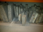
Laser-engraving the print plates.
This was something which I wanted to invest time exploring, I am due to lead a teaching course in laser-cut and letterpress back home this Autumn! I wanted to look at how the plates could be etched for both etchings relief printmaking, it was a lengthy process. I chose to use an acrylic plastic as it would hold the image better and not go soggy like MDF or plywood, it also avoided the inevitable smouldering which wood gives. It does let off a terrible smell.
Papermaking V2.
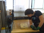
I happened to be cycling past Gonzaga university one day. I noticed a couple of students who were making paper out on the campus fields. They had a machine for blending fabric into paper mulch, something which I had tried once before in Bristol. By coincidence, the department had recently worked with paper-artist Drew Mattot, from the Peace Paper Project, who had lead a similar workshop I attended, in Bristol three years previously. Matt Rude, the art lecturer at Gonzaga kindly lent me his equipment and space. Thanks to a pure cotton bed sheet, I was able to pull some beautiful feeling sheets.
He showed me how to double-cooch the paper (sounds funny, yes), but essentially pull one sheet of paper, then lay on the circuits, before pulling a second and laying it on top.
As the paper is compressed and rolled out the fibres of the two sheets join, trapping the circuits within.
This part was super successful. I only had an issue with one sheet, which I took apart later and glued back together, for some reason the water and PVA mixture managed to oxidise the copper.
Binding an electronic book.
Initially, I had wanted to use a traditional bookbinding form (see model one). However, when it came down to working out the circuit for this, how the switches would be toggled when the pages open and how this would connect to each pin, it seemed a complete headache.
I switched quite quickly to a Japanese Stab Stitch binding. I wanted the conductive thread to connect the pins to each relevant Arduino pin, to stay true and utilise the form of the book in the circuits. I also found later that I had to include four transistors in the heating elements, so I wanted to take advantage of the aesthetic of these components and have them on show.


The Heating Element
I took this from fellow Laboratory resident, Liza Stark’s, previous research into heating elements. She had used this circuit countless times with TIP120s with no problem. However, in this form I was finding that it was hard to get enough voltage to provide enough heat, the diode was overheating and the transistor. After a little bit of research, I discovered a few issues:
1. I had been using a silver thread, which in some cases was causing the circuit to short, which would work OK as long as the program allowed enough time for the switch to be open.
2. The TIP120 has a voltage drop of about 1-2v at 0.5A (or something like that, if I have this wrong then a constructive email is cool – don’t troll me) and a MOSFET is far lower 0.004V. Also, a TIP120 is slower to switch, so I imagine when running with a PWM it is less efficient.
3. As the circuit was essentially shorting, the diode was storing a lot of the current – therefore prone to overheating.
I don’t think I perfected this, but I did manage to get it working.
MP3 player
I went for a MINIDFPlayer, which is available all over the internet for a very low price. This seemed to e great, working better with the command function than any available libraries (The best I found was the fastminiplayer by …. But I found it still ended up confusing the other parts of my code).
But then disaster struck, for some unknown mystical reason, it stopped working, as did my other spare. It was a completely baffling, night-before the show nightmare. No reason at all in the circuitry, nothing in the program. It was bizarre. Liza Stark somehow managed to run this code through it, and for some reason, it kicked it back into action… A few hours later the same happened to two of hers she was using on her project, and for some reason running the same thing had the same result.
Finally
TIME (or the lack of it)
As is often the case, I ran out of time. I was only able to piece together a prototype, with all the components there, but not quite debugged. Under normal circumstances, I know it takes me one month to make a book, so with electronic components, two should do it right? Right!??
Nope, well almost. So close I can taste it. All in all, I was proud of the way this turned out, but I have got some good old refinement to do on it. I can’t complain; it was another huge learning experience, which is what I feel this residency was all about.
Links:
Thermal Tape: https://www.carbonheater.us/
Less EMF (hilarious): http://www.lessemf.com/


")